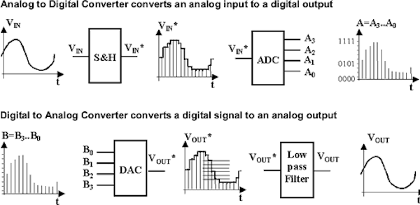

The transfer function of an ADC is a plot of the voltage input to the ADC versus the code's output by the ADC. For example, quantization error will appear as the noise floor in an FFT plot of a measured signal input to an ADC, which I'll discuss later in the dynamic performance section). Further, quantization error will appear as noise, referred to as quantization noise in the dynamic analysis.

Maximum quantization error is determined by the resolution of the measurement (resolution of the ADC, or measurement if signal is oversampled). Quantization error is an artifact of representing an analog signal with a digital number (in other words, an artifact of analog-to-digital conversion). DC accuracy, and resulting absolute error are determined by four specs-offset, full-scale/gain error, INL, and DNL. This error cannot be avoided in ADC measurements. These four specifications build a complete description of an ADC's absolute accuracy.Īlthough not a specification, one of the fundamental errors in ADC measurement is a result of the data-conversion process itself: quantization error. The ADC specifications that describe this type of accuracy are offset error, full-scale error, differential nonlinearity (DNL), and integral nonlinearity (INL). In such applications, the measured voltage is related to some physical measurement, and the absolute accuracy of the voltage measurement is important. Many signals remain relatively static, such as those from temperature sensors or pressure transducers. In this case, the DC accuracy of a measurement is prevalent so the offset, gain, and nonlinearities will be most important.

In another example, a system may measure a sensor output to determine the temperature of a fluid. In this design, the engineer will be most concerned with dynamic performance specifications such as signal-to-noise ratio and harmonic distortion. Here, the concern is the measurement of a signal's power (at a given set of frequencies) among other tones and noise generated by ADC measurement errors. The application determines which specifications the designer will consider the most important.įor example, a DTMF decoder samples a telephone signal to determine which button is depressed on a touchtone keypad. Most applications use ADCs to measure a relatively static, DC-like signal (for example, a temperature sensor or strain-gauge voltage) or a dynamic signal (such as processing of a voice signal or tone detection). The ADC performance specifications will quantify the errors that are caused by the ADC itself.ĪDC performance specifications are generally categorized in two ways: DC accuracy and dynamic performance. ADC measurements deviate from the ideal due to variations in the manufacturing process common to all integrated circuits (ICs) and through various sources of inaccuracy in the analog-to-digital conversion process. This guide will help engineers to better understand the specifications commonly posted in manufacturers' data sheets that describe the performance of successive approximation register (SAR) ADCs.ĪDCs convert an analog signal input to a digital output code. But to select the correct ADC for an application, it's essential to understand the specifications. Confused by analog-to-digital converter specifications? Here's a primer to help you decipher them and make the right decisions for your project.Īlthough manufacturers use common terms to describe analog-to-digital converters (ADCs), the way ADC makers specify the performance of ADCs in data sheets can be confusing, especially for a newcomers.


 0 kommentar(er)
